 |
| The frame, fully assembled, with trays |
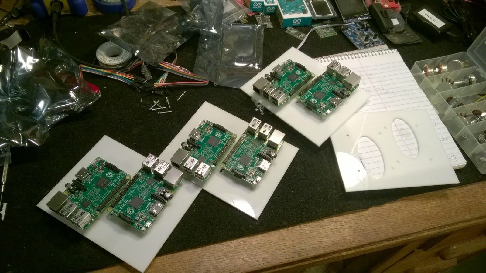
It's hard to play with a Raspberry Pi and not wonder what a bunch of them wired together could do. We're talking about $40 computers with 1GB RAM, a quad-core 900MHz processor, and a GPU, all on a credit card-sized board. They're not too far off, specs-wise, from the ThinkPad X60 I'm typing this post on. All that with a $40 price tag -- how could you not want as many as possible?
It probably wouldn't surprise anyone who knows me to learn that I've been working on doing exactly this: wiring a bunch of Raspberry Pis into a cluster for distributed computing. I've now collected enough of the hardware that the big priority is building a rack to keep it all organized. There are a bunch of cool Pi cluster rack designs out there. One 3D-printed design stands out in particular, both for the idea behind it and the implementation. I considered a few different designs, but none were a perfect match for my goals. In the end, it seemed like the best option was to roll my own rack.
Every design is tuned to the resources available to its designer. Being at my family's house for a week over winter break, I had a seven-day window of access to my dad's wood shop, his CNC machine, and his help. Naturally, I was inclined to take full advantage of all three. First of all, though, came deciding what exactly it was we would make.
Design
A few different design constraints are involved here. I wanted every Pis easy to access or remove. I wanted the finished product to look nice. I wanted to keep the footprint small, because this thing is probably going to live on my desk. It was also important to make sure the design wouldn't restrict airflow, because this cluster will be running some long jobs without any heat sinking. Lastly, budget dictated an eight-board setup.
I decided to power over USB, because my understanding is that the Pi has a protective self-resetting fuse in line with the USB power input. This fuse keeps power supply malfunctions from permanently destroying your board, but powering over GPIO seems to bypass this protection. I didn't put too much time into verifying this info, since I heard it from a trusted source, and in any case powering the boards over USB from a couple externally powered hubs is also nice and simple. If I ever decide to overclock these boards (and, let's be real, that's happening sooner or later), I'll probably enlist some help and make a custom power supply to deal with the increased power demands at that point. Maybe mount some heat sinks, too.
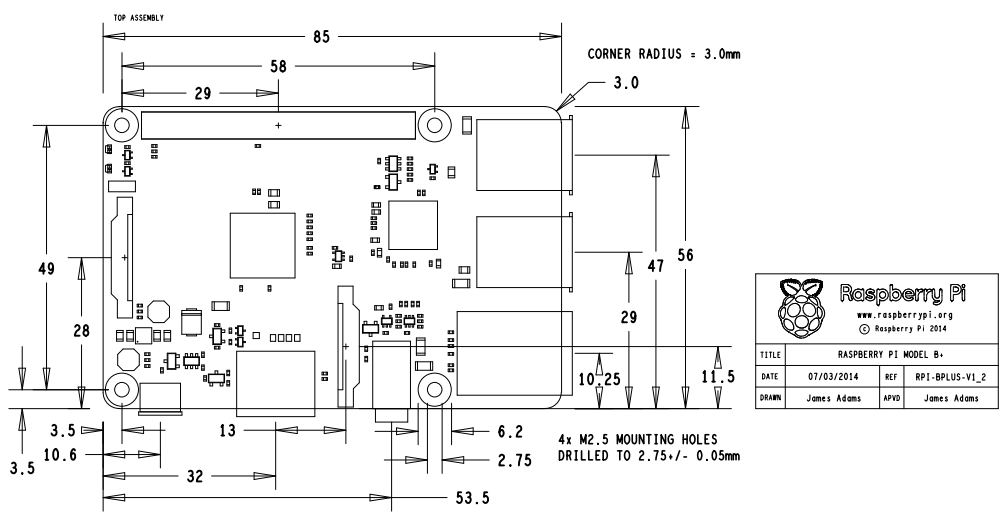
These parameters together with the tools available led me to the design you saw above. It's a vertical rack of five trays: on the bottom, a tray for USB hubs and an 8-port Ethernet switch; above it, four trays, all set up to mount two Pis each. Each Pi mount point also has an elliptical hole to promote airflow. It seemed important not to neglect either side of the boards ventilation-wise, since both sides of the Pi 2 have important chips on them (CPU and GPU on top, RAM on bottom). The Pis are rotated 180 degrees from each other, so that both have their Ethernet port and USB power input exposed.
 |
| The final design. |
Assembly
It was only in hindsight that I realized how simple this process really is. The vast majority of our time was spent not on woodworking but on trying to troubleshoot the CNC machine toolchain. There don't seem to be nearly enough mature open-source projects in this domain. This is an area where a few dedicated programmers could make a respectable impact. The process of setting up a working toolchain was so painful that I'm not going to say another word about it, except to note for posterity that when we did get things working it was using the proprietary tools provided by the manufacturer (Shapeoko) start-to-finish. One wishes that there could be a better way.
 |
| The CNC machine, hard at work cutting a tray. Not pictured: hours and hours of troubleshooting. |
The sides were easy enough to build: just take the relevant cut-to-size pieces (after sanding them reasonably smooth!), measure out whatever ground clearance you might want, glop some wood glue onto the points of contact, press everything together, slap on some clamps, and let it sit for a good long while.
 |
| Letting it sit. |
Cutting the slots is easy, too, if there's a tablesaw around: just measure & mark the slot locations, lower the blade so it extends from the table by however deep you want the slots to be, and gouge away. I opted to be sort of generous with the cut depth (after all, better too wide than too narrow), but what I've come to realize is that the tolerance used here has a surprisingly big impact on how cleanly the trays slide in. It pays to be as accurate as possible.
Once the slots are cut, it's time to glue up the other four crosspieces and bring the whole frame together. This step was a bit tricky, since all four beams have to be left to set at roughly the same time in order to keep everything nicely aligned, which turns out to be easier said than done. The problem is that once two pieces are in and clamped down, the remaining ones get progressively harder to wedge in without losing most or all of their wood glue. I really don't have any better advice than to use generous amounts of glue (remember that spillover can always be cut/scraped/sanded off) and to have two pairs of hands involved: one person gently pulling the soon-to-be contact points apart, and another person to put the new beam in and get it lined up just right.
 |
| Do not disturb. |
Once this glue cures, the frame's complete except for backstops. These really could not be easier to attach, especially compared to what came before them.
After that, all that's left to do is sand this puppy damn smooth and slap on some finish. This wood took the finish well, each coat drying pretty quickly. We put on ballpark four or five coats (who counts?), continuing until it looked good, then sanded it down and added a final layer.
 |
| A delicate process. |
Oh -- there is one more thing left to do, and that's to mount the Pis on their trays. As you can see, we hit a slight gotcha here:
 |
| Asymmetry... adds character? |
If you think it looks like those boards are missing half their standoffs, you're absolutely right. Here's what happened. We drew up our parts list for screws, standoffs, nuts, and washers, and rolled on down to the local hardware store (Stone Way Hardware, great place). Tracking down the 2.5mm hardware took a while, since just about nobody except computer & electronics hobbyists use this stuff... arguably for good reason. Turns out the stock was pretty sparse. We asked if they might have more "in the back". No such luck. The clerk commented, after hearing the amounts we were looking for, that we wanted as many of these components as they sold in about two years. He didn't seem particularly moved by the chance to get two years ahead of quota, and so we had to make due with half of everything.
Fortunately, it only really takes two screws & standoffs to do a "good enough" job of mounting a Pi if you install them diagonally from each other. It's not pretty, but it works. The boards are mounted and stable now, but I definitely plan to get the rest of the hardware at some point down the road. It'd probably be better for the boards, and it'd just look better besides. Maybe I'll check back in at Stone Way in a couple years.
 |
| The rack, with a network switch in its tray and 6 out of 8 Pis mounted |
Sohliloquies: Making A Raspberry Pi Cluster'S Rack >>>>> Download Now
ReplyDelete>>>>> Download Full
Sohliloquies: Making A Raspberry Pi Cluster'S Rack >>>>> Download LINK
>>>>> Download Now
Sohliloquies: Making A Raspberry Pi Cluster'S Rack >>>>> Download Full
>>>>> Download LINK l6